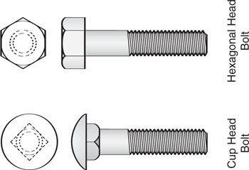
Cup head bolts are generally used to fasten timber members together or to fix plates and fittings to timber. The square section at the base of the head is driven into the wood to prevent the bolt from turning when the nut is being tightened.
These are general purpose bolts used for a wide range of applications in all mechanical and structural trades and industries and are available in mild steel or high tensile steel for automotive and structural work.
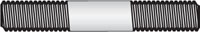
Engineers studs are used when a part is to be fixed to a surface, the reverse side of which is inaccessible preventing a bolt and nut from being used. One end is drilled and tapped into the surface, the stud is then screwed in and the part secured with a nut.
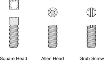
Set screws are used for securing pulleys to shafts or for coupling parts together. A spanner is used to tighten the square head set screw. An Allen key is used to tighten the Allen head set screw and a screw driver is used to tighten the grub screw.
There are many other types of bolts and machine screws used in industry. Some of them take their name from the shape of the head and some from the purpose for which they are used.
Metalthreads are general purpose machine type screws that are used in a variety of metalworking applications.
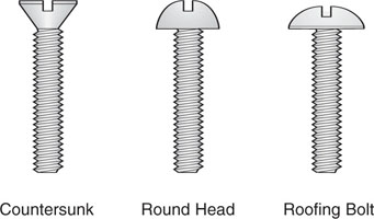
Countersunk metalthreads are used where the head is to be flush with the surface.
Round head metalthreads are generally used for fixing materials that are too thin to countersink.
Roofing bolts have a larger, flatter head than round head metalthreads and are used to fix thin sheet metals as well as for general applications.
Before leaving this page, think of what you've just been reading, and test yourself with these questions.
[[ mc /f ][ How are cup-head bolts prevented from rotating? ][ * With glue ][ * With a hexagonal section ][ With a square section ][ * With a slotted head ][ The bolt has a square section that gets driven into the wood. ]]
[[ mc /f ][ How do you secure an engineer's stud into a surface? ][ With a nut ][ * With loctite ][ * With a cross-thread ][ * With a tap ][ A nut is placed behind the surface and tightened against it. ]]
[[ mr /f ][ What types of heads do set screws have? ][ Square ][ Slotted ][ * Hexagonal ][ Allen key ][ Set screws don't usually have a hexagonal head. ]]
[[ mc /f ][ Which of these would you probably not use to fix thin sheetmetal? ][ Countersunk metalthread ][ * Round head metalthread ][ * Roofing bolt ][ The countersunk head assumes that the metal has some thickness. ]]
[[ sh ][ NUTS ]]|
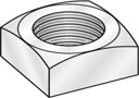
Square nuts are general purpose nuts often used on cup head bolts as well as other applications. |
 |
|
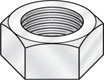
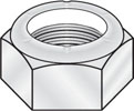
Hexagonal nuts are general purpose nuts used in the majority of engineering and mechanical applications. Both open end and ring type spanners can be used on a hexagonal nut. |
 |
|
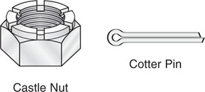
Castle nuts feature a raised up section which is slotted to receive a cotter pin. The illustration on the right shows a castle nut and cotter pin. |
 |
|
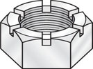
Slotted nuts are simply hexagonal nuts slotted to take a cotter pin. They are used in the same way as castle nuts. |
 |
|
Self locking nuts have nylon or fibre inserts which lock the nut when the thread of the bolt cuts its way into the softer material. |
 |
|
Dome nuts or acorn nuts are used when it is necessary to cover the end of the bolt to improve appearance. | 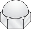 |
|
Wing nuts are used in situations where hand tightening is required. | 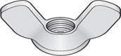 |
|
Flat washers or plain washers provide a seat for a nut or a bolt head. These washers are often used as packing or spacers. | 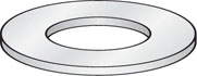 |
Before leaving this page, think of what you've just been reading, and test yourself with these questions.
[[ mc /r /f ][ Which of these nuts will keep the bolt thread clean and free of rust? ][ Dome nut ][ * Castle nut ][ * Slotted nut ][ * Wing nut ][ The dome nut keeps dirt and other contaminants off the end of the thread. ]]
[[ mc /r /f ][ Which of these nuts can usually be tightened without a spanner? ][ Wing nut ][ * Dome nut ][ * Castle nut ][ * Self-locking nut ][ Wing nuts can be tightened by hand. ]]
[[ mc /f ][ What is the purpose of a cotter pin? ][ To secure the nut to the bolt ][ * To make it easier to remove the nut later ][ * To let you tighten the nut by hand ][ * To keep the thread clean ][ A cotter pin is a security device for nuts and bolts ]]
[[ sh ][ LOCKING DEVICES ]]Vibration and movement can sometimes loosen a nut. Locking devices are used to prevent nuts from working loose.
|
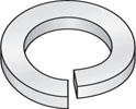
These are split washers, made from spring steel. Spring washers are twisted so they compress and place pressure back on the nut when it is tightened down. The split ends may also bite into the nut as it tends to loosen. |
 |
|
Both external and internal tooth lock washers have twisted teeth which act in the same way as the spring washer. There are several different types of tooth lock washers available, some of which are called star washers. | 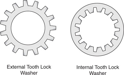 |
|
The illustration on the right shows a cotter pin fitted to a slotted hexagonal nut. The cotter pin is fitted through a hole in the bolt or shaft. The slot in the nut holds the cotter pin and prevents the nut from turning and becoming loose. | 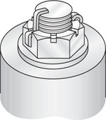 |
|
Lock nuts are often thinner than standard nuts as shown in the illustration on the right. However, it is quite common to use a standard nut as a lock nut. The locking action is caused by tightening one nut against the other. | 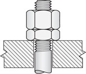 |
|
Keys are used to secure components such as gears and pulleys to a shaft or spindle. Keys are usually made from steel and are fitted with precision into grooves called keyways. The illustration on the right shows a typical square key and its keyway. | 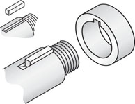 |
|
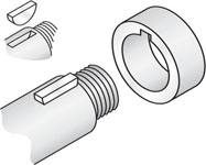
The illustration on the right shows a woodruff key and its keyway. The keyway is cut on a milling machine with a special circular cutter. The woodruff key provides greater resistance against the thrust of the part on the shaft because it fits into a deeper groove due to its almost semi-circular shape. |
 |
Circlips are spring steel rings which fit into grooves, usually in shafts or spindles and are designed to prevent the part being held from coming off the shaft.
|
Internal circlips fit into grooves cut into the inside of holes and expand in diameter when placed in their grooves. | 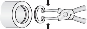 |
|
External circlips fit into grooves cut on the outside of a shaft and they contract in diameter when placed in their grooves. |
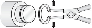 |
The illustrations of internal and external circlips above, show special circlip pliers which are used to expand or contract circlips when they are being fitted into their grooves or being removed.
Before leaving this page, think of what you've just been reading, and test yourself with these questions.
[[ mr /r /f ][ Which of these locking devices can you use on a 'normal' nut and bolt? ][ Spring washer ][ Tooth lock washer ][ * Cotter pin ][ Lock nut ][ Spring washers, tooth lock washers and lock nuts can all be used on normal nuts and bolts. ]]
[[ mm /f ][ Match the type of locking device with what it locks into: ][ Cotter pin ~ Hole ][ Circlip ~ Groove ][ Woodruff key ~ Slot ][ Cotter pin = Hole ; Circlip = Groove ; Woodruff key = Slot ]]
[[ sh ][ SPANNERS ]]Spanners are used in the workshop for a variety of purposes such as assembly of components and setting or adjusting tools and machines. The most appropriate spanner should always be selected for a particular job. It should fit the nut perfectly and allow the job to be done quickly and efficiently.
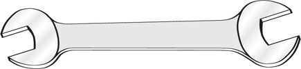
Open end spanners have a U-shaped opening at each end. The opening fits neatly across the opposite flats of the nut or bolt head whose size is stamped on that end of the spanner. Open end spanners usually have a different size at each end.
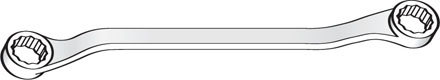
The ring spanner has sockets at each end which grip all faces of a hexagonal nut.
The ring spanner is useful in confined spaces where a full swing is not possible. Most ring spanners have a different size at each end.
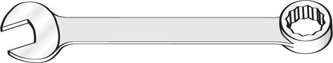
The combination spanner has a socket at one end and an open end spanner at the other. Each end of the combination spanner fits the same size nut.
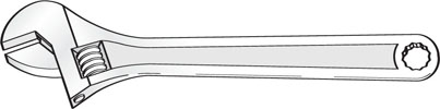
The adjustable spanner is often called a shifting spanner or sometimes a crescent spanner.
It has a movable jaw which can be adjusted to fit a range of sizes. Where available, a fixed spanner should generally be used in preference to an adjustable spanner because there is less chance of damaging the nut.
|
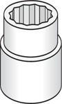
Sockets, or socket spanners fit all faces of a hexagonal nut or bolt head. They are usually purchased in sets which contain a range of sizes. Sockets are used in conjunction with a variety of handles and extensions. |
 |
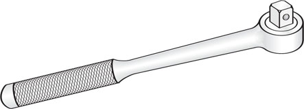
Ratchet handles, or wrenches, are used in conjunction with sockets to provide the quickest action of all hand operated spanners.
The ratchet action allows the operator to rotate the handle forward and backward, tightening or loosening the nut without having to lift or reposition the spanner.
Before leaving this page, think of what you've just been reading, and test yourself with these questions.
[[ mc /f ][ Which of these would be best for applying a large turning force onto a nut? ][ A socket ][ * An open-end spanner ][ * A ring spanner ][ * An adjustable spanner ][ Sockets are best for applying large torques to nuts and bolts. ]]
[[ mc /f ][ Which of these is best for easily changing the turning direction of a nut or bolt? ][ A socket and ratchet handle ][ * An adjustable spanner ][ * An open-ended spanner ][ * A combination spanner ][ The ratchet handle can quickly reverse its direction. ]]
[[ sh ][ LEVERS ]]The principle of the lever is used in many different types of machines from the most complex industrial equipment to the simple pair of pliers.
The most common mechanical application of the lever principle is to move loads or perform work far in excess of the effort applied. This implies that there is an advantage gained by the use of such a machine. This advantage is usually called the mechanical advantage.
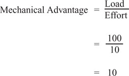
The mechanical advantage is found by dividing the resistance overcome by the force exerted and be can expressed as a ratio. For example, if a load (resistance) of 100kg can be moved by an applied effort of 10kg the mechanical advantage can be calculated as shown below:
If a lever such as a crow bar is used to move a heavy object it should be placed so that minimum effort is required. The longer the lever used the less effort is required to move the load. Placing the pivot point closer to the load will also reduce the effort required.
A lever is a rigid bar arranged or used in such a way that it can turn about a pivot point or fulcrum. There are three forces acting in the operation of a lever.
The relationship of these forces will vary according to the type or order of the lever. First, second and third orders are terms used to describe different types of levers.
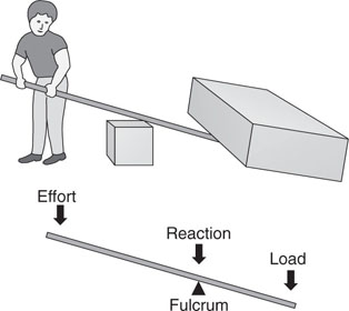
A first order lever means the fulcrum or pivot point is somewhere between the effort applied and the load.
In this order the reaction at the fulcrum equals the sum of the load (resistance overcome) and the effort applied.
The illustrations on the right demonstrate this principle. Other examples of first order levers are prising the lid off a paint tin, and operating pliers, tin snips and a see-saw.
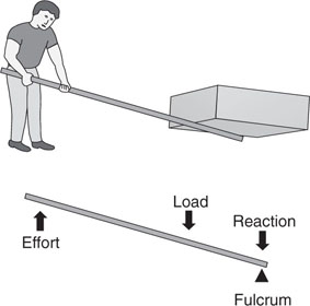
In the second order, the load and effort are on the same side of the fulcrum. The effort required is still less than the load and the reaction at the fulcrum equals the resistance overcome minus the effort applied.
The illustrations on the right show a second order situation. Other examples of second order levers are a wheel barrow and a nut cracker.
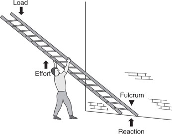
In the third order the load and effort are located on the same side of the fulcrum but the load is further from the fulcrum than the position of the applied effort. In this case the effort required is greater than the load.
The illustration on the right shows a third order situation where a long ladder is being placed against a wall. Other examples of third order levers are using a hand shovel and the human forearm.
Extra mechanical advantage can be gained by coupling levers together so that the mechanical advantage of one lever is used to apply much greater effort to the second lever, therefore enabling the double action lever to overcome a much greater resistance with even less effort.
The bolt cutter shown on the right is a typical example of double action levers. Bolt cutters can cut through steel bars with very little effort.

Before leaving this page, think of what you've just been reading, and test yourself with these questions.
[[ mc /r /f ][ Which of these is a good example of a first-order lever? ][ A pair of scissors ][ * Your forearm ][ * A wheelbarrow ][ First-order levers have the pivot point in the middle. ]]
[[ mc /r /f ][ Which of these is a good example of a second-order lever? ][ A wheelbarrow ][ * A pair of scissors ][ * Your forearm ][ Second-order levers have the load in the middle. ]]
[[ mc /r /f ][ Which of these is a good example of a third-order lever? ][ Your forearm ][ * A pair of scissors ][ * A wheelbarrow ][ Third-order levers have the effort in the middle. ]]
[[ mc /f ][ Which of these levers does not give you a mechanical advantage? ][ Your forearm ][ * A pair of scissors ][ * A pair of nutcrackers ][ * A wheelbarrow ][ Your forearm uses more effort than the load, but you get an action benefit. ]]
[[ sh ][ PULLEYS ]]The invention of the wheel was a very important event in the history of the development of machines. Some early applications would have been the potter’s wheel in cottage industry and wheels for carts and chariots in transport.
The wheel is of little practical value without an axle on which it can rotate. The wheel and axle is therefore considered as a unit in terms of the mechanical principle involved.
The wheel provides rotary motion which is a very important concept incorporated in the design of machines. A mechanical advantage can be gained using the wheel and axle principle. An example would be the steering mechanism of a car or truck.
The steering wheel moves through a greater radius than the shaft which connects the steering wheel to the steering box. Therefore the driver has the advantage that the actual work done is much less than that required to manually move the wheels of a car.
Most machines, particularly those driven by electric motors or internal combustion engines incorporate the wheel and axle principle in the driving mechanism as well as in other mechanical functions of the machine.
Pulleys revolve on a shaft or axle and therefore operate on the wheel and axle principle.
A pulley can be considered as a wheel fixed to a shaft and is used in conjunction with a belt. Belts and pulleys transmit rotary motion and power from one shaft to another, usually placed a reasonable distance apart.
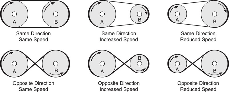
The speed of the driven shaft can be changed by changing the ratio of the pulley diameters. The direction of rotation can by changed by using a different belt arrangement.
The following diagrams illustrate changes in speed and direction.
Belts and pulleys are used in mechanical applications where a slight amount of slipping can be tolerated. In some situations slipping may even be a necessary part of the mechanical operation. The main types of pulleys are listed below.
|
Flat pulleys are rarely used today with the possible exception of some agricultural machinery. Flat pulleys are in fact slightly rounded to prevent the flat belt from running off. The illustration on the right shows the rounded face of the ‘flat’ pulley. |  |
|
V pulleys or V-belt pulleys are made to suit the shape of a V belt as shown in the illustration on the right. The V belt tends to slip much less than the flat belt resulting in more positive drive. The belt grips the pulley on two faces and wedges itself into the pulley as it rotates. | 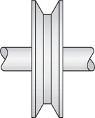 |
|
The illustration on the right shows two V-belt pulleys secured to the same shaft. Double pulleys are sometimes required when the load is too great for a single belt. Excessive load will cause the belt to stretch or even break. Additional pulleys and belts share the load. | 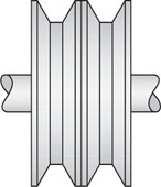 |
|
Step cone pulleys consist of a series of pulleys of different sizes arranged on a shaft with a corresponding set of pulleys on the opposite shaft. Step cone pulleys are used when the speed of rotation needs to be changed from time to time. The largest diameter pulley on one shaft is opposite the smallest diameter pulley on the other shaft. | 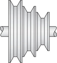 |
|
Rope pulleys are manufactured with a concave semicircular surface to fit the shape of a rope or circular belt. Some household appliances have circular belts which run on pulleys of this type. Rope pulleys are also used in pulley blocks as described below. | 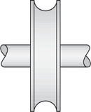 |
|
Rope pulleys are often used for lifting loads. The pulleys are generally housed in pulley blocks which can contain one or more pulleys. The illustrations on the right show single and double sheave pulley blocks. | 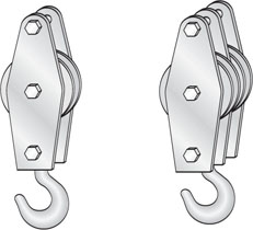 |
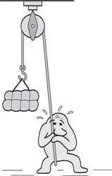
If a single pulley is used to lift a load the only gain is a change of direction. There is no mechanical advantage to make the work easier for the operator. The illustration below left shows a cartoon character struggling to lift a heavy load using a single pulley.
If two pulleys are used a mechanical advantage is gained. The illustration below right shows the cartoon character lifting the load with much less effort using two pulley blocks.
 |
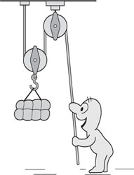 |
With two pulleys arranged in tandem the load is raised only half the distance when the operator pulls the rope downward. For example, if the rope is pulled down 600mm the load is lifted only 300mm.
If more than two pulleys are used a greater mechanical advantage is gained but the rate at which the load is raised is substantially reduced.
Before leaving this page, think of what you've just been reading, and test yourself with these questions.
[[ mc /f ][ How should I arrange pulley wheels and a belt to achieve reverse motion and higher rotating speed? ][ Cross-belt, smaller driven wheel ][ * Straight-belt, smaller driven wheel ][ * Cross-belt, larger driven wheel ][ * Straight-belt, larger driven wheel ][ Crossing the belt reverses the direction, smaller driven wheels rotate faster. ]]
[[ mc /f ][ Complete this statement: Flat belts usually run on _____ ][ Slightly round-faced wheels ][ * Slightly groove-faced wheels ][ * Perfectly flat-faced wheels ][ * V-faced wheels ][ Flat belts run on slightly round-faced wheels. ]]
[[ mr /f ][ What are the mechanical benefits of lifting a load with a multi-wheel pulley system? ][ Load and effort are in different directions ][ Effort can be less than the load ][ * Loss of mechanical advantage ][ * Avoidance of friction ][ Multi-wheel pulleys provide advantages in effort and direction. ]]
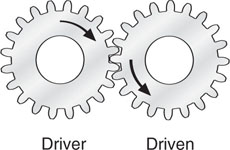
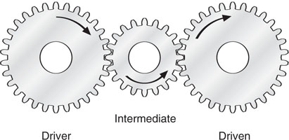
[[ sh ][ GEARS ]]Gears are used to transmit motion and power with positive drive between two shafts a short distance apart. Gears in contact revolve in opposite directions but if shafts are to rotate in the same direction an intermediate gear must be used between the driver gear and the driven gear.
The illustration below left shows two gears that are in contact. The driver gear is rotating in a clockwise direction. This causes the driven gear to rotate in an anti-clockwise direction.
The illustration below right shows an intermediate gear placed between the driver and driven gears. The driven gear then rotates in the same direction as the driver gear.
 |
 |
Gears that mesh must have teeth of the same size, irrespective of the diameter of the gear wheel. If the driven gear or shaft is to rotate at twice the speed of the driver, the driver gear must have twice as many teeth as the driven gear. In other words, the ratio of gear speeds is inversely proportionate to the ratio of the number of teeth.
In the illustration below, driver gear A has 40 teeth and driven gear B has 20 teeth.
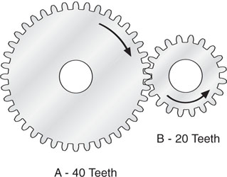
Therefore gear B rotates at twice the speed of gear A but in the opposite direction.
For example, if gear A rotates at 250 RPM, gear B will rotate at 500 RPM.
In the illustration below, the driver gear C has 20 teeth and driven gear D has 60 teeth.
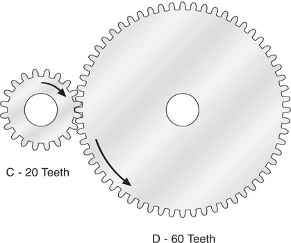
Therefore gear D rotates at one third the speed of gear C but in the opposite direction.
For example, if driver gear C rotates at 600 RPM, driven gear D will rotate at 200 RPM.
Using an intermediate gear to rotate the driven gear in the same direction as the driver gear does not change the ratio of speeds between the driver gear and the driven gear.
In the illustration below the driver gear E has 40 teeth and driven gear F has 20 teeth.
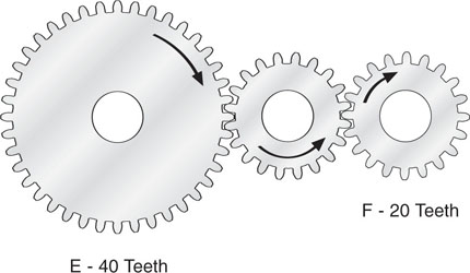
No matter how many teeth in the intermediate gear, driven gear F will still rotate at twice the speed of the driver gear E.
|
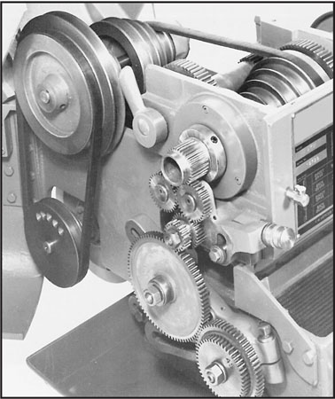
Spur gears are wheels with teeth that are straight and parallel to the axis of the gear. They are the normal gears for driving parallel shafts. Spur gears have been used for the examples in the previous section which covers gear rotation, gear ratios and speed. A typical example of spur gears can be found in the change gears of a belt drive metal lathe. The photograph on the right shows the drive mechanisms of a small metal lathe. The rotational speed of the lead screw can be changed by fitting a different set of change gears. The speed of the main shaft or headstock spindle can be changed by shifting the V-belt which drives the spindle, to a pair of pulleys that will give a higher or lower speed. |
 |
Many different types of gears are used in the design and manufacture of machines, automobiles and other mechanical devices. For example, bevel gears are used to connect shafts which form an angle to one another, helical gears have teeth which twist around a cylinder and worm gears are used to connect non-intersecting shafts at right angles to each other.
All moving machine parts such as gears must be lubricated. By reducing friction lubrication reduces wear.
No surface is absolutely smooth and when two surfaces are put together there will always be some interlocking between the surfaces.
The introduction of a suitable lubricant such as oil actually separates the surfaces providing oil to surface contact and significantly reducing wear.
Before leaving this page, think of what you've just been reading, and test yourself with these questions.
[[ mc /f ][ If you want both the driving gear and the driven gear rotating in the same direction, what arrangement of gear wheels do you need? ][ One intermediate gear wheel ][ * Two intermediate gear wheels ][ * Driven gear larger than the driving gear ][ * Driven gear smaller than the driving gear ][ One intermediate gear wheel will do the trick. ]]
[[ mc /r /f ][ Your driving gear has 20 teeth, while your driven gear has 40 teeth. If your driving gear turns at 50 rpm, how fast will your driven gear turn? ][ 25 rpm ][ * 40 rpm ][ * 50 rpm ][ * 100 rpm ][ 50 x 20 / 40 = 25 rpm ]]
[[ mc /f ][ You wish to reduce rotation and reverse direction by using a 30-tooth driving gear and a 60-tooth driven gear. Do you also need an intermediate gear? ][ No ][ * Yes ][ * It depends on how fast you run the gears ][ * Not if you use oil ][ The simple answer is no. ]]