ELECTRICITY - B
[[ sh ][ A BRIEF HISTORY ]]
- The effects of static electricity had been known since about 600 BC.
- About 1600 AD Dr William Gilbert, Court Physician to Queen Elizabeth I, observed that a force was generated by rubbing an amber rod with wool.
- He noticed that the amber rod was then capable of attracting light objects. The word ‘electric’ has been derived from the Greek word ‘elektron’ which means ‘amber’.
- In 1752 Benjamin Franklin, when flying a kite in a thunderstorm, discovered that lightning was an electrical discharge.
- During the 19th century many scientists around the world were developing theories and experimenting with electrical energy.
- For example, Volta of Italy made the first cell that produced electricity and Ampere of France developed the science of electromagnetism.
- Michael Faraday, in 1831 discovered that an electrical pulse could be generated by moving a magnet in and out of a coil.
- In 1879 Thomas Edison perfected the first incandescent electric lamp. This was the first major step in taking electricity from the laboratory to the home and factory.
Reflect and Respond
Before leaving this page, think of what you've just been reading, and test yourself with these questions.
[[ so /f ][ Place these significant scientists in historical order: ][ William Gilbert ][ Ben Franklin ][ Alessandro Volta ][ Michael Faraday ][ Thomas Edison ][ Gilbert => Franklin => Volta => Faraday => Edison ]]
[[ mc /f ][ Which of these scientists investigated "static" electricity?][ Gilbert ][ * Franklin ][ * Edison ][ * Faraday ][ Gilbert rubbed amber rods with wool - a classic school science experiment involving static charges. ]]
[[ mc /f ][ Which of these scientists created the first "battery"? ][ Volta ][ * Ampere ][ * Edison ][ * Faraday ][ Volta made the first "cell" - the proper name for what we often incorrectly call a "battery". ]]
[[ sh ][ ELECTRON THEORY ]]
No one knows exactly what electricity is. It is weightless, yet it can lift or haul thousands of tonnes of material. It is shapeless yet it is everywhere. We can’t see it, yet it produces light. Scientists do know, however, what electricity does and how to harness it.
The electron theory, briefly described below, has been developed from observations of the behaviour of electricity and is the basis for most scientific studies in this area.
The Atom
All matter is made up of atoms. Atoms are very small, for example it takes millions of them to make a speck of dust.
|
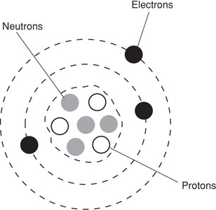
The diagram on the right illustrates the structure of an atom comprising the following sub-atomic particles:
- Electrons that are negatively charged.
- Protons that are positively charged.
- Neutrons that are neutral.
The negative charge of the electron is equal to the positive charge of the proton. The protons and neutrons form a closely packed group called the nucleus.
If the atom is not disturbed and no electrons are removed from the space around the nucleus, the atom itself is neutral. If electrons have been removed the remaining structure is positively charged and is called a positive ion. A negative ion is an atom which has gained extra electrons. |
 |
Electrical Conductors
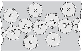
Matter which contains a relatively large number of free electrons which may be moved from atom to atom is an electrical conductor.
|
Substances in which electrons are not free to move when a moderate force is applied are electrical insulators.
Most of the metals are electrical conductors and most non-metals such as plastics are electrical insulators.
The diagram on the right illustrates a greatly magnified section of an electrical conductor.
|
 |
Electric Current
Nature acts to restore the balance of electrical charge whenever possible. If a negatively charged object is connected by a conductor such as copper wire to a positively charged object, the excess electrons in the negative object will move in the conductor towards the positive object until the balance is restored.
This movement of electrons is called electric current. The ampere (amp) is the unit of measurement for the strength of an electric current.
Electrons in a conductor are never completely free to move, therefore some work has to be done to move them. The property of interfering with the flow of electrons is called resistance and is measured in units called ohms. Good electrical conductors have little resistance and poor conductors have much resistance.
If electrons are to move against this resistance it is necessary to supply them with energy. Energy which can be converted into electron motion is called electromotive force or voltage. The unit of measurement for electromotive force is the volt.
Reflect and Respond
Before leaving this page, think of what you've just been reading, and test yourself with these questions.
[[ mc /f /r ][ Which atomic particle is positively charged? ][ The Proton ][ * The Neutron ][ * The Electron ][ * The Nucleus ][ Protons are positively charged particles; the Nucleus is positively charged, but it's a collection of particles. ]]
[[ mc /f /r ][ What is the unit of electric current? ][ The Ampere ][ * The Ohm ][ * The Volt ][ * The EMF ][ Current is measured in Amps (from the word Ampere) ]]
[[ mr /f /r ][ Which of these substances do NOT conduct electricity well? ][ Rubber ][ Plastic ][ * Metal ][ Cork ][ Most metals conduct well; most non-metals do not conduct. ]]
[[ sh ][ PRODUCING ELECTRICITY ]]
Luigi Galvani, an Italian, in 1792 observed an unusual twitching reaction when two dissimilar metals came into contact with a frog’s leg. What had occurred was a small flow of electricity.
Chemical Methods
Alessandro Volta later developed Galvani’s discovery and constructed the first practical means of producing electrical energy from chemical energy. The ‘voltaic’ cell consists of a zinc rod and a copper rod partly immersed in dilute sulphuric acid and connected with a wire conductor through which an electric current flows.
The copper rod is called the positive electrode (anode) and the zinc rod the negative electrode (cathode) and the sulphuric acid is called the electrolyte solution. The action of the zinc atoms dissolving in the acid causes a loss of electrons and the zinc atoms become positively charged zinc ions. The electrons flow in the wire conductor from the zinc rod to the copper rod.
The electrons enter the electrolyte solution from the copper electrode where they combine with hydrogen ions to form hydrogen atoms which are given off in the form of hydrogen gas. The zinc gradually dissolves in the acid but the performance of the cell will deteriorate before the zinc and acid are used up.
|
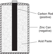
Modern dry cell batteries, such as those used in torches, operate on the same principle by dissolving zinc in an acid paste (usually ammonium chloride). The illustration on the right represents a section through a dry cell battery.
The zinc rod of the voltaic cell is replaced by a zinc can which contains the acid paste and a carbon rod which replaces the copper rod of the voltaic cell.
A flow of electrons is produced when the zinc dissolves in the acid paste. |
 |
A car battery also produces electricity by chemical change. The generator or alternator causes chemical processes to take place resulting in electrical energy being stored in the battery for use in the electrical circuits of the car. A car battery contains acid and plates made from lead.
Using Magnetism
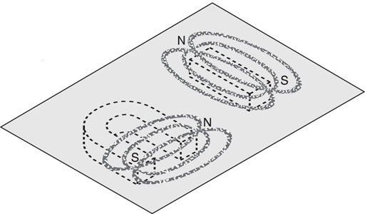
The magnetic field present around the poles of a magnet can be shown by using iron filings on a piece of cardboard as illustrated below.
The iron filings align themselves in magnetic lines of force between the north and south poles of the magnets which are positioned below the cardboard. It is these magnetic lines of force which produce an electric current in a conductor.
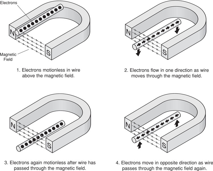
When a wire is passed close to a magnet the magnetic lines of force cause electrons to flow in a certain direction in the wire. When the wire moves in the opposite direction, the electrons in the wire flow in the opposite direction.
However, electrons in the wire flow inside a magnetic field only when there is motion. If the wire was brought to a stop while crossing the magnetic lines of force electricity would cease to flow.
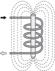
The following illustrations demonstrate the relationship that exists between the magnetic field, electrons and motion.
The pulse of electricity produced by passing a wire through a magnetic field would not be enough to light the smallest bulb. However if a coil of wire is rotated through a magnetic field at high speed a flow of electricity can be produced.
The strength of the current will depend on:
- The strength of the magnetic field.
- The length of wire in the coil (number of turns).
- The speed of rotation of the coil through the magnetic field.
An increase in any or all of these factors will increase the strength of the electric current produced.
Modern methods of generating electricity depend on the basic principles described above.
Reflect and Respond
Before leaving this page, think of what you've just been reading, and test yourself with these questions.
[[ mc /f ][ Which way do the electrons flow in Volta's original copper / zinc / acid battery? ][ * From the copper anode to the zinc cathode ][ * From the copper cathode to the zinc anode ][ * From the zinc anode to the copper cathode ][ From the zinc cathode to the copper anode ][ Electrons flow from the (negative) zinc cathode to the (positive) copper anode. ]]
[[ mc /f /r ][ What is the conducting rod in the centre of a dry cell made of? ][ Carbon ][ * Zinc ][ * Ammonium ][ * Copper ][ Dry cells use a conducting carbon rod as an electrode ]]
[[ mr /f ][ The strength of current produced in a coil rotating in a magnetic field depends upon ... ][ The speed of rotation ][ * The thickness of the wire ][ The strength of the field ][ The length of the wire ][ The thickness of the wire doesn't directly affect the size of the current, but the resistance of the wire would. ]]
[[ sh ][ ELECTROMAGNETISM ]]
When a wire is passed through a magnetic field an electric current flows in the wire. Conversely, when a wire has a current flowing through it, the wire sets up a magnetic field around itself. This field is called an electromagnetic field.
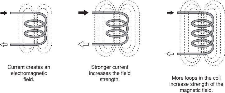
The field near a single wire which carries an electric current is too weak for most useful purposes, but if the wire is wound into a coil the same current will produce a much stronger electromagnetic field. Each loop of the coil creates its own field therefore strengthening the total electromagnetic field around the coil.
The strength of the field can be increased by increasing the strength of the current passing through it or by increasing the number of loops or turns in the coil as shown in the illustrations below.
The illustration below right shows a piece of soft iron placed in the coil. The magnetic lines of force are concentrated in this iron core which becomes magnetised. When the current is switched off the soft iron core loses its magnetism. This iron core is called an electromagnet.
|
Permanent magnets can be made from hard steel and some metal alloys.
When manufactured, steel and alloys are not magnetised, but when placed in a strong magnetic field large numbers of electrons are induced to move in one direction and the material is said to be magnetised.
These hard materials will retain their magnetism when the electric current is switched off, however a soft iron core will lose its magnetism rapidly.
Electromagnets are used in generators, electric motors, starter motors and many other products and appliances. |
 |
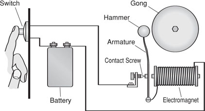
The electric bell is a simple application of an electromagnet. The diagram below illustrates the basic circuit and operation of a simple electric bell.
When the switch is pressed, current flows in the circuit and the soft iron core of the electromagnet becomes magnetised and draws the armature to it, causing the hammer to strike the gong.
As the armature moves, contact is broken at the contact screw, the iron core loses its magnetism, the hammer springs back to its original position and the cycle starts again. While the switch is on the hammer moves back and forth.
Reflect and Respond
Before leaving this page, think of what you've just been reading, and test yourself with these questions.
[[ mr /f ][ How can you make a stronger magnetic field with a coil of current-carrying wire? ][ By increasing the number of turns ][ By increasing the current in the wire ][ By winding the coil around a soft iron rod ][ * By placing the coil under water ][ * By winding the coil around a carbon rod ][ Neither water nor carbon will improve the magnetic field strength. ]]
[[ mc /f ][ In the bell circuit, where does the circuit "break" when it is working? ][ Between the contact screw and the armature ][ * Between the battery terminals ][ * Between the armature and the gong ][ * Between the coils of wire in the electromagnet ][ The armature "breaks" contact with the screw when the electromagnet pulls it away. ]]
[[ sh ][ CURRENT FLOW ]]
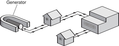
The diagrams which follow illustrate the analogy between the flow of electricity and the flow of water.
|
In the illustration below left, electrical energy flows from the generator to the buildings where it is used to operate lights and machines, then it is returned to the generator.
Why is a wire needed to return the electricity to the generator? |
 |
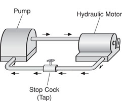
The following illustration may help in understanding why this is so. If water is pumped into a pipe and a secure plug is placed in the other end of the pipe, the water will cease to flow. Regardless of the amount of pressure built up by the pump, the water will still not flow.
|
The illustration on the right shows a different situation where the water will flow in a closed system of pipes connecting a pump and a hydraulic motor. The circuit of pipes allows the water to flow continuously through the system until the stopcock (tap) is closed.
An electrical generator can be thought of as a kind of pump. It is a machine which creates a pressure (voltage) which makes electrons move or flow in the wire.
If a wire does not make a complete circuit then the flow is stopped. |
 |
Regardless of the amount of pressure or voltage generated, the electrons will not flow.
Direct and Alternating Current
If the electrons flow continuously in one direction along a conductor, the current is said to be direct current or DC. This is the type of electrical current produced by a battery or DC generator.
If the electrons flow firstly in one direction, then back in the opposite direction and continue this back and forth motion the current is said to be alternating current or AC. This type of current is produced by an alternator or AC generator and is the type of electricity found in home electrical circuits.
Reflect and Respond
Before leaving this page, think of what you've just been reading, and test yourself with these questions.
[[ mr /f ][ Which of these sources of electricity produce DC? ][ Batteries ][ Generators ][ Solar Cells ][ * Alternators ][ Alternators produce alternating current or AC; all the rest produce DC ]]
[[ sh ][ SYMBOLS, CIRCUITS & SAFETY ]]
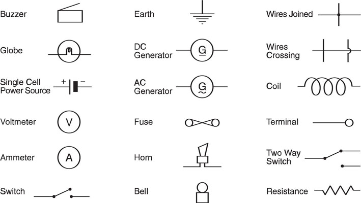
Some Electrical Symbols
Electrical symbols are simple graphic representations of electrical components that are used when electrical circuits are being drawn.
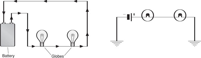
Series Circuits
When circuit components are connected with only one connecting path they are said to be connected in series as shown in the following diagrams.
In a series circuit the same current is in all components. When batteries are connected in series the voltage obtained in the circuit is the sum of the voltage in the batteries. For example a torch might have four 1.5 volt batteries connected in series to give a total of 6 volts.
If resistors are placed in series the resistance in the circuit will be equal to the sum of the resistors.
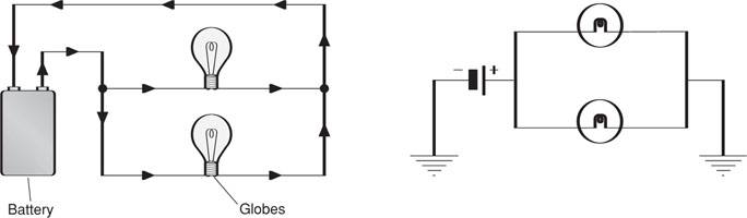
Parallel Circuits
When circuit components are connected with several conducting paths they are said to be connected in parallel as shown in the following diagrams.
If batteries are connected in parallel the circuit voltage remains the same as in each cell. For example, if four 1.5 volt batteries were connected in parallel, the circuit voltage would be 1.5 volts.
Parallel circuits are used in home wiring. There are as many circuits as there are appliances to be run and each appliance receives the same voltage.
If resistors are wired in parallel, then each resistor uses only the power required for its own purpose.
Open & Closed Circuits
It is desirable that electrical circuits can be used when necessary and the current stopped when not required. To enable this to be done without dismantling part of the circuit each time, a switch is usually placed in the circuit.
When the switch is in the off position there is a break in the circuit and electrons cannot flow. This is called an open circuit. When the switch is in the on position the electrons can flow and it is called a closed circuit.
In your home, light bulbs and other appliances are connected in parallel with each other. If one bulb is broken or switched off, current can still pass through other bulbs and appliances connected in parallel with it.
If a number of light bulbs were connected in series and one bulb was broken the circuit would be open and current could not flow. Therefore none of the bulbs would light up.
Safety
Electricity is potentially very dangerous to human life, but it can be used safely if reasonable precautions are taken. The following are a few simple precautions that should be observed in everyday use of electricity.
- Never use an appliance with a cracked plug or damaged cord.
- Keep liquids away from electrical equipment and never use equipment with wet hands or in wet conditions. Minerals and other substances in water cause it to be an electrical conductor.
- Switch off before removing plugs.
- Do not touch a live element, such as in a toaster, with a metal object.
- Leave all repairs of appliances and home wiring to a qualified electrician.
- Restrict your own experiments and projects to a safe level, for example 15 volts maximum.
Reflect and Respond
Before leaving this page, think of what you've just been reading, and test yourself with these questions.
[[ mc /f ][ In a series circuit with two light bulbs, what is guaranteed to always be the same? ][ The current in the bulbs ][ * The brightness of the bulbs ][ * The resistance of the bulbs ][ * The voltage across the bulbs ][ In a series circuit, the current is the same through both bulbs. ]]
[[ mc /f ][ In a parallel circuit with two light bulbs, what is guaranteed to always be the same? ][ * The current in the bulbs ][ * The brightness of the bulbs ][ * The resistance of the bulbs ][ The voltage across the bulbs ][ In a parallel circuit, the voltage is the same across both bulbs. ]]
[[ mm /f ][ Match the following circuit expressions with the most likely description: ][ Closed Circuit ~ a correct, complete circuit for current ][ Open Circuit ~ a deliberately broken circuit where nothing flows ][ Short Circuit ~ a circuit with an accidental faulty path for current ][ Open circuits are switched off; closed circuits are switched on; short circuits are faulty. ]]
[[ mr /f ][ Which of the following statements about household electric circuits are correct? ][ Power points are wired in parallel with each other ][ Light switches are wired in series with light bulbs ][ * Power points are wired in series with each other ][ * Light switches are wired in parallel with light bulbs ][All power points supply the same voltage, therefore are parallel ]]
[[ sh ][ CHANGING ELECTRICITY ]]
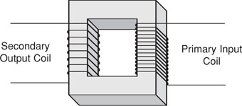
Transformer
The purpose of a transformer is to increase or decrease the value of an alternating voltage. Transformers consist of a soft iron core on which are wound two coils of insulated wire. These coils are known as the primary and secondary windings.
The alternating voltage which is to be changed is the input and is connected to the primary coil. The output, which is the required voltage, is produced in the secondary coil.
The voltage produced in the secondary coil will generally depend on:
- The primary voltage.
- The ratio of the number of turns in the secondary coil to the number of turns in the primary coil.
If an alternating voltage of 12 volts is required from 240 volts, a step down transformer is used in which the primary coil has 20 times the turns of the secondary coil. In this example 240 volts is applied to the primary coil and 12 volts is produced at the terminals of the secondary coil.
Because the secondary coil has only one twentieth the number of turns in the primary coil the output voltage is one twentieth the input voltage.
If an increase in voltage is required a step up transformer is used in which the number of turns in the secondary coil is greater than the number of turns in the primary coil.
Rectification
A rectifier is a device which enables direct current to be produced from an alternating current. However it cannot work in reverse. A rectifier cannot produce an alternating current from a direct current.
A simple metal rectifier consists of stacked copper discs alternated with larger metal plates to radiate the heat developed in the discs during the rectification process.
Alternate sides of the copper discs are oxidised giving a series of copper/copper-oxide boundaries at which rectification takes place.
A diode is also widely used as a rectifier.
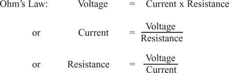
Ohm’s Law
Ohm’s law describes the relationship between current, voltage and resistance in an electrical conductor.
Ohm’s law is usually expressed as:
V = I x R
where I is the current measured in amperes, V is the electromotive force or voltage measured in volts and R is the resistance measured in ohms.
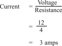
For example, if a battery supplies 12 volts and the circuit has a resistance of 4 ohms, the current flowing through the circuit can be calculated as follows:
Reflect and Respond
Before leaving this page, think of what you've just been reading, and test yourself with these questions.
[[ mc /f ][ A transformer has a turns ratio of 12:1. If the primary voltage is 240V, what will the secondary voltage be? ][ * 12V ][ * 1V ][ * 240V ][ 20V ][ The secondary voltage will be 1/12 of the primary voltage, hence 240/12 = 20V ]]
[[ mc /f ][ Why are rectifiers necessary? ][ Because household power is AC, but many devices are DC ][ * Because household power is DC, and many devices are AC ][ * Because rectifiers are used to make smaller voltages ][ * Because rectifiers are needed to make diodes ][ Mains electricity is supplied as AC, but most electronic devices need DC. ]]
[[ mc /f ][ If a resistance of 5 ohms has a current of 4 amps flowing through it, what voltage is across the resistance? ][ 20 volts ][ * 1 volt ][ * 1.25 volts ][ * 9 volts ][ voltage = current x resistance = 4 x 5 = 20 volts ]]
[[ sh ][ BASIC ELECTRONIC COMPONENTS ]]
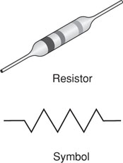
Resistors
These components used in electronic circuitry are neither conductors nor insulators but are somewhere in between allowing some current to flow in varying degrees. The lower the resistance the more current can flow in the circuit.
Generally, resistors are used to limit the supply of current to the amount required by certain components in a circuit. In some cases too much current is likely to damage components.
|
Fixed value resistors are not polarised, which means they can be connected either way around in a circuit.
The amount of resistance in a resistor of this type is denoted by a system of coloured bands on the body of the resistor as shown in the illustration on the right. |
 |
Variable resistors are versatile components which have a special sliding arm that allows the amount of resistance to be varied. The volume control on a radio is a typical example of a variable resistor in an electrical circuit. Alternative symbols are shown below.
Diodes
There are several different types of diodes used in electronic circuitry and all have one basic feature in common.
They allow current to flow in one direction only. It is this feature which allows some diodes to be used a rectifiers.
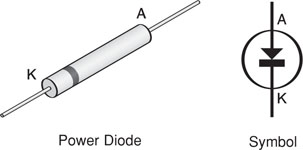
Power diodes are used in electronic circuits to protect components against possible damage which may be caused by accidental reversing of the electric current. For example, if a battery is wrongly connected to the circuit.
The band on one end of the diode indicates which way the diode is to be connected in the circuit. In the symbol shown above, the arrow is the positive or anode (A) side of the diode and the bar is the negative or cathode (K) side.
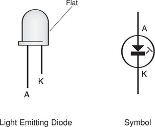
Light emitting diodes glow brightly when they are correctly connected in a circuit. If they are connected incorrectly with the polarity reversed, light emitting diodes may be damaged.
The polarity is usually shown in two ways. The longer lead is the positive side and the shorter lead the negative side. The body of the LED often has a flat on the side near the negative lead.
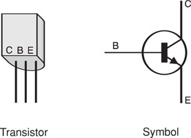
Transistors
Transistors are components which control and amplify electric current. Most transistors have three leads, all of which must be connected correctly for the transistor to operate.
These leads are called the base (B), the collector (C) and the emitter (E) as shown in the illustrations below.
Transistors can be used as very fast switches in a circuit and they can also be used to amplify.
If a certain amount of current is fed into the base lead a larger current is made to flow into the collector and then out of the emitter.
For example, in a transistor radio a very weak radio signal can be amplified thousands of times because the transistors can produce a greatly amplified copy of the signal in the current which flows between the collector and the emitter.
The diagrams above illustrate one of the common types of transistors used in electronic circuitry.
Capacitors
Capacitors are components which are capable of storing an electrical charge. The higher the capacitance the more electric charge the capacitor can store.
The capacitor has the ability to supply electricity from its stored charge as required. Capacitors are often called condensers.
The main parts of a capacitor are two fine metal plates which are insulated from each other and usually wound into a cylindrical shape. These plates can be charged and discharged as required.
Capacitors are usually marked with their capacitance or storage capacity and a voltage rating. If the voltage rating is exceeded the capacitor may be seriously damaged.
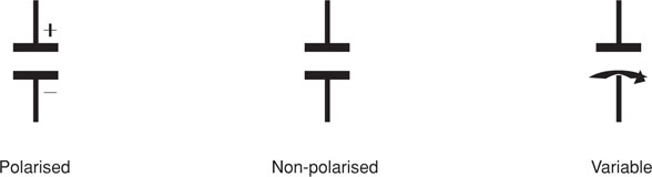
There are many different types of capacitors which can be classified into three main groups:
- Polarised capacitors which are marked positive and negative.
- Non-polarised capacitors which may be connected either way in a circuit.
- Variable capacitors in which the storage capacity can be altered by turning a shaft which changes the position of two sets of inter-leaving plates.
Symbols for the three types of capacitors are shown below.
Reflect and Respond
Before leaving this page, think of what you've just been reading, and test yourself with these questions.
[[ mc /f /r ][ Which of these devices can be used as switches? ][ Transistors ][ * Resistors ][ * Capacitors ][ * Diodes ][ Transistors can be used to amplify and to switch. ]]
[[ mc /f /r ][ Which of these devices can be used to store electrical energy? ][ * Transistors ][ * Resistors ][ Capacitors ][ * Diodes ][ Capacitors store electric charge on their metal plates. ]]
[[ mr /f /r ][ Which of these devices are available as both fixed and variable devices? ][ * Transistors ][ Resistors ][ Capacitors ][ * Diodes ][ Both resistors and capacitors are available in fixed and variable forms. ]]
[[ mc /f /r ][ Which of these devices can be used as a light source? ][ * Transistors ][ * Resistors ][ * Capacitors ][ Diodes ][ Some diodes are Light Emitting Diodes (LEDs). ]]